Week 3 - Computer controlled cutting
Objectives for the week:
Group assignment:
- To characterize your lasercutter's focus, power, speed, rate,
kerf, joint clearance and types
Link for Group Assignment
Individual assignment:
-To cut something on the vinylcutter
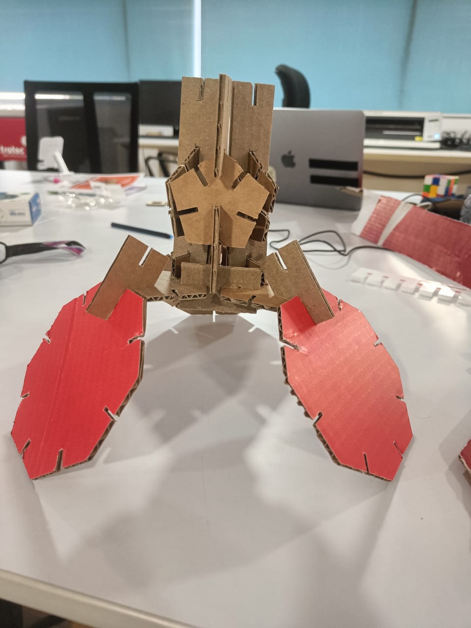
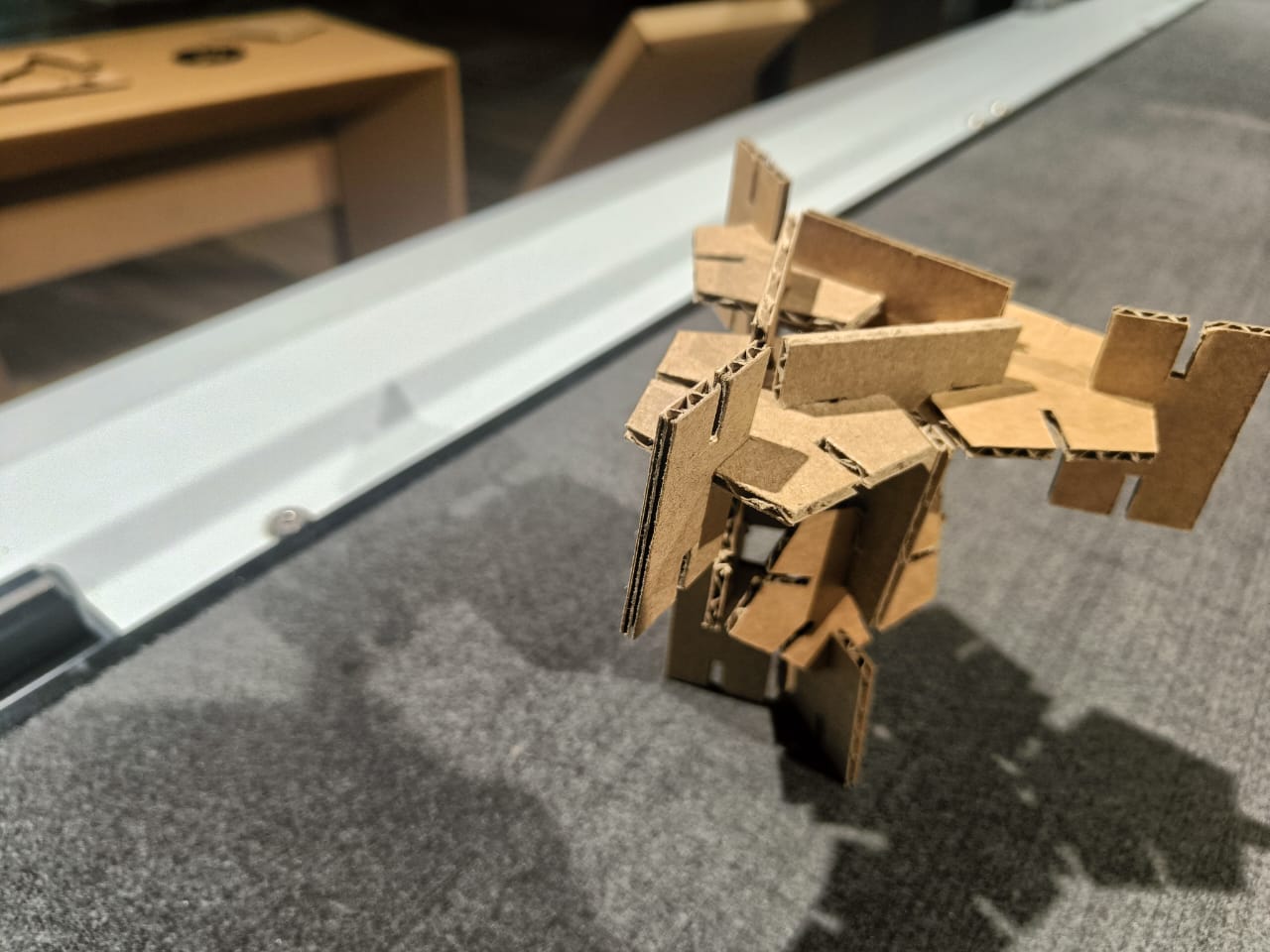
- To design, lasercut, and document a parametric construction kit,
- To account for the lasercutter kerf, which can be assembled in multiple ways
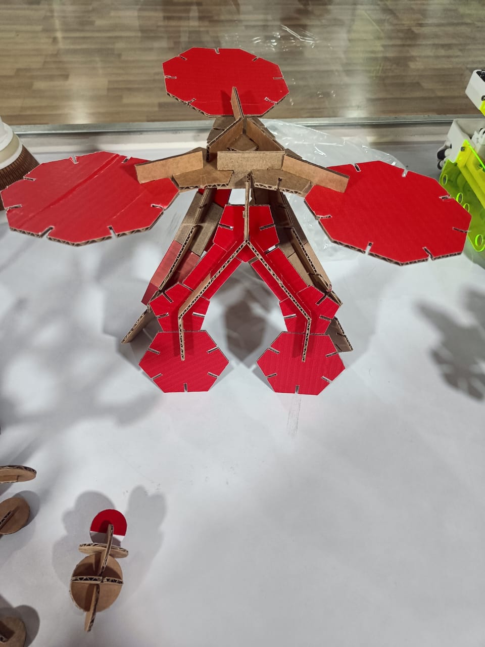
For extra credit include elements that aren't flat
About cutting with knife:
Zund uses active mode of cutting.
Path planning of vinyl cutter
Tangential element of cutting direction
Slope change in cutting with a knife
Laser cutter:
Basics of laser:
Why is a laser different from normal light beam?
Laser is different from normal light beam as it is
- monochromatic (same wavelength)
- coherent (same phase angle, waveform and frequency)
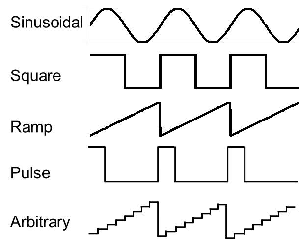
Different types of waveforms:
- collimated (travelling in a straight line)
Lasers are comprised of three main components:
- The energy source pumps light into a gain medium. It varies according to the type of laser. It could be a laser diode, an electrical discharge, a chemical reaction, a flash lamp, or even another laser.
- The gain medium emits light of a specific wavelength when excited by light. It is said to be the source of optical gain. Lasers are typically named after their gain medium. In a CO2 laser for example, the gain medium is CO2 gas.
- The resonator amplifies the optical gain through mirrors that surround the gain medium. These include bulk mirrors in solid-state lasers, cleaved or coated facets in laser diodes, and Bragg reflectors in fiber lasers.
Population inversion - A state in which a system exists in a state in which more members of the system are in higher, excited states than in lower, unexcited energy states.
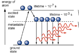
Laser pumping - Laser pumping refers to introducing energy into a laser system to produce a population inversion, where there are more atoms or molecules in an excited state than in the ground state.
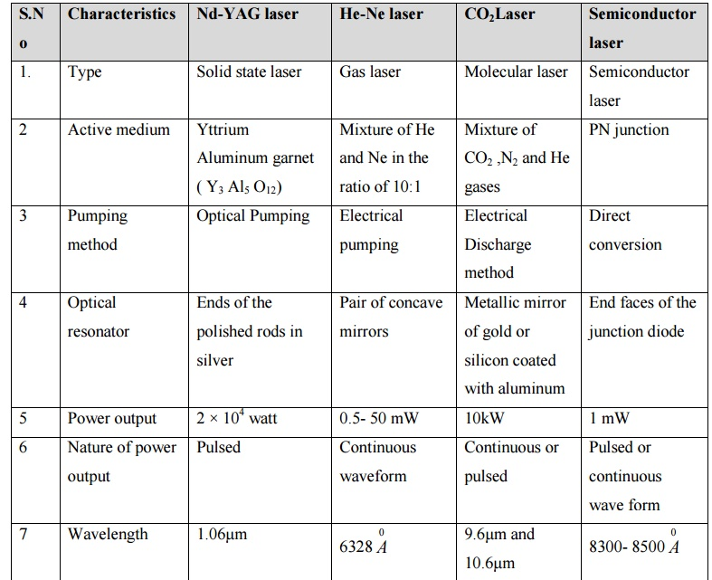
Types of laser and their differences:
Different types of lasers are needed for these applications. Based on their gain medium, lasers are classified into five main types:
- Gas Lasers - electric current is sent through a gas to generate light; e.g., carbon dioxide (CO2) lasers, helium–neon lasers, argon lasers, krypton lasers, and excimer lasers.
- Gas lasers are used in a wide variety of applications, including holography, spectroscopy, barcode scanning, air pollution measurements, material processing, and laser surgery.
CO2 lasers are probably the most widely known gas lasers and are mainly used for laser marking, laser cutting, and laser welding.
- Gas lasers are used in a wide variety of applications, including holography, spectroscopy, barcode scanning, air pollution measurements, material processing, and laser surgery.
- Solid-State Lasers - a solid (crystals or glasses) mixed with a rare earth element as their source of optical gain (a process where the medium transfers part of its energy to the emitted electromagnetic radiation, resulting in an increase in optical power). The mixed element is typically neodymium, chromium, erbium, thulium, or ytterbium.
- Applications: material processing applications. LIDAR technology as well as various medical applications, including tattoo and hair removal, tissue ablation, and kidney stone removal.
- Fiber Lasers
In fiber lasers, the gain medium is an optical fiber (silica glass) mixed with a rare-earth element.
The light guiding properties of the optical fiber are what makes this type of laser so different: the laser beam is straighter and smaller than with other types of lasers, making it more precise. Fiber lasers are also renowned for their small footprint, good electrical efficiency, low maintenance and low operating costs.
Fiber lasers are used in a range of applications, including material processing (laser cleaning, texturing, cutting, welding, marking), medicine, and directed energy weapons.
Examples of fiber lasers used for these applications include ytterbium and erbium-doped fiber lasers.
- Liquid Lasers (Dye Lasers)
Optical gain medium: organic dye in liquid form.
Used in laser medicine, spectroscopy, birthmark removal, and isotope separation.
Advantages - can generate a much wider range of wavelengths, making them good candidates to be tunable lasers, meaning that the wavelength can be controlled while in operation.
In laser isotope separation for example, lasers are tuned to specific atomic resonances. They are then tuned to a specific isotope to ionize the atoms, making them neutral as opposed to negatively or positively charged. They are then separated with an electric field, achieving what is called isotope separation.
- Semiconductor Lasers (Laser Diodes)
Similar to regular diodes in that they have a positively-negatively (PN) charged junction.
Difference: laser diodes have an intrinsic layer at the PN junction made of materials that create spontaneous emission. The intrinsic layer is polished so that the generated photons are amplified, ultimately converting the electric current into laser light.
Semiconductor lasers that do not use the diode structure, such as quantum cascade lasers and optically pumped semiconductor lasers.
Like fiber lasers, laser diodes can be classified as solid-state lasers since their gain medium is solid. However, they are in a category of their own because of their PN junction.
Laser diodes are often used as energy sources to pump other lasers. These lasers are referred to as diode-pumped lasers. In these cases, laser diodes are typically arrayed to pump more energy, as shown in the following image.
Laser diodes are extremely common. They are used in barcode readers, laser pointers, laser printers, laser scanners, and several other applications.
Additionally, these five types of lasers can be divided into subcategories based on their mode of operation: continuous-wave lasers and pulsed lasers.
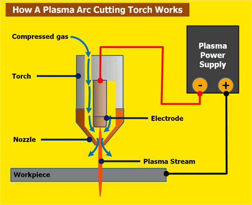
Plasma Cutting:
Basics of Plasma Cutting:
Plasma cutting (plasma arc cutting) is a melting process in which a jet of ionised gas at temperatures above 20,000°C is used to melt and expel material from the cut. During the process, an electric arc is struck between an electrode (cathode) and the workpiece (anode).
Metal cutting can be categorised into two – mechanical and thermal cutting. Plasma cutting is a thermal cutting method where ionised gas is used for cutting the metal.
Plasma is an electrically conductive ionised gas-like substance. This means that some atoms are missing electrons and there are also free electrons floating around.
A gas can be transformed into plasma by subjecting it to intense heating. That is why plasma is often called an ionised gas.
Plasma cutters use compressed air or other gases, such as nitrogen. Ionisation of these gases takes place to create plasma.
Typically, the compressed gases come into contact with the electrode and then ionise to create more pressure. When the pressure builds up, a stream of plasma is pushed towards the cutting head.
The cutting tip constricts the flow to create a stream of plasma. This is then subjected to the workpiece. As plasma is electrically conductive, the workpiece is connected to the ground through the cutting table.
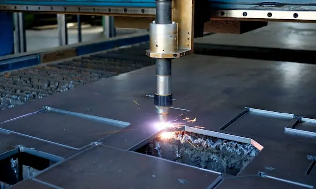
As the plasma arc contacts the metal, its high temperature melts it. At the same time, the high-speed gases blow away the molten metal.
Cutting workpiece by burning using plasma.
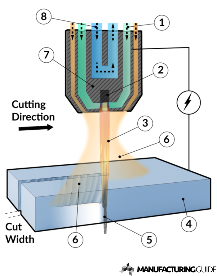
The process
By plasma cutting we mean precision plasma which has now adays become the most common used in controlled machines instead of conventional plasma cutting. Ptrecision plasma has better tolerances and less angular deviation on the seat but lower max cutable thickness.
A power source is connected to the work [1] and the cutting tool electrode [2], which is often made of tungsten. The cutting tool also includes cooling water [3] and a plasma gas [4] adjusted to the workpiece.
By the energy supplied gas is transformed into plasma resulting in temperatures of about 30,000 degrees Celsius. The plasma beam [5] emitted melts the workpiece and by its high kinetic energy, the material is removed, leaving behind a cut.
The cutting head is positioned by means of a gantry system.
By nesting details can be placed in a way that minimizes wastage of material.
Laser engraving vs Laser cutting:
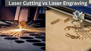
LE: Feed Rate - H; Power - H; Pulse - High
LC: Feed Rate - Low; Power - High; Pulse - Low
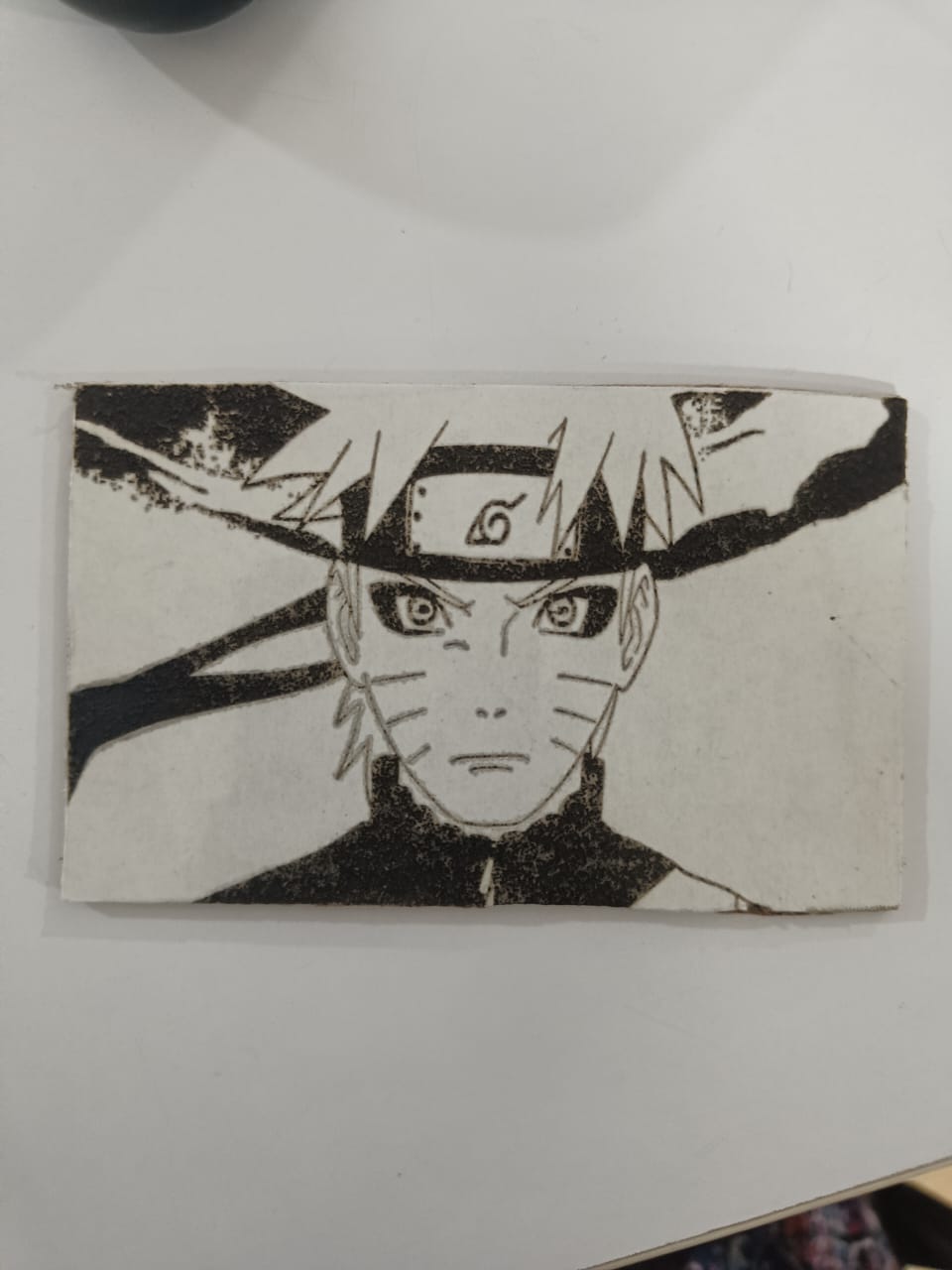
My attempt at laser engraving:
Water Jet: Abrasive Cutting
What is Water Jet Cutting?
Water jet cutting is a manufacturing process that uses high pressure jets of water provided by pressurizing pumps that deliver a supersonic stream of water to cut and shape various types of materials. The water in water jet cutting is pressurized to 392 MPa and projected using a small precision nozzle. As the water leaves the nozzle, it reaches speeds that are three times the speed of sound.
Pure water jet cutting with water as its medium is designed for soft materials such as wood, plastics, foam, paper, and rubber. When an abrasive is added to the water stream, such as titanium, stainless steel, aluminum, glass, ceramic material, and concrete, cutting becomes more aggressive and capable of cutting hard metals.
How Water Jet Cutting Works
The water jet cutting process can be completed in several different ways. The majority of the methods have an abrasive blended into the water to cut particles from the workpiece. It is a very versatile manufacturing process that can be used to cut, shape, and design a workpiece to meet exact specifications.
The shaping method used for water jet cutting has several advantages over other cutting processes, such as plasma or laser. Water jet cutting has better accuracy, can cut complex designs, and is able to cut thermally sensitive surfaces. The abrasive is like sandpaper and erodes the material being cut. It does not heat the material or change its temper. The cut edges are clean and can be welded without the need for further processing.
The Process of Water Jet Cutting
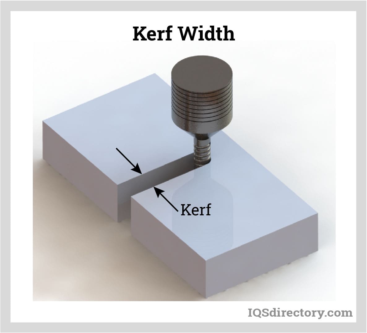
Measuring Kerf Width
Kerf width relates to the material being removed as a part of a cutting process. The term was originally used to refer to the material removed by the cutting of a saw blade. In the case of a water jet cutter, it refers to the width of the stream, which is normally 0.04 inch or smaller. The inside corners cut by water jet cutting have a radius that matches the width of the stream. The kerf depends on a variety of factors, which include material thickness, type of material, cutting quality, and the nature of the waterjet nozzle.
The size of the kerf is an important design factor that has to be accounted for when determining the dimensions of the final product. If the kerf is 0.042 inches, the dimensions of the final part have to be adjusted to account for the cutting width or the final part will be 0.042 inch off.
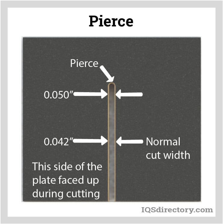
Initial Water Jet Piercing
The first cut made by a water jet cutter is referred to as the pierce, which is wider than the normal kerf. The initiation of the pierce is the first step in the water jet cutting process. It can be completed in several different ways with stationary, linear, circular, and low pressure being the most common methods. Which of the piercing methods is used is dependent on the material to be cut and the amount of scrap produced.
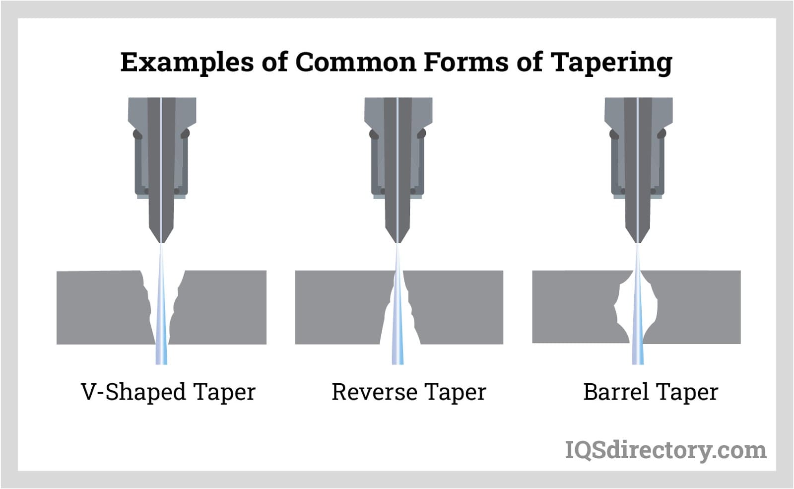
Tapering in Kerf Width
Tapering in water jet cutting refers to the kerf width at the top of the cut and its width at the bottom. Water jet cuts have a V-shaped taper, which is generated because the stream loses some of its energy as it cuts deeper into the material, with more material being removed at the top than at the bottom.
Slow cutting speeds produce a reverse taper where the kerf width is wider at the bottom, which is caused by removing more material at the bottom of the cut. The reverse taper can be seen when cutting soft, pliable materials.
Barrel tapers are created when the cut is widest in the middle of the cut, which occurs when cutting extremely thick materials.
For most cutting, tapering does not matter and can be used as a benefit for certain jobs. In the case of precision tooling where cut pieces must fit together accurately, tapering can be a problem and needs to be taken into consideration.
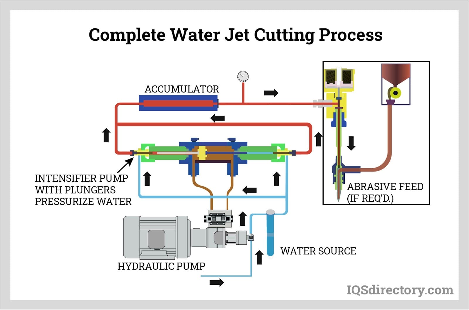
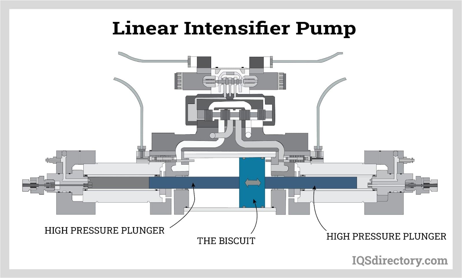
Pressurizing the Water
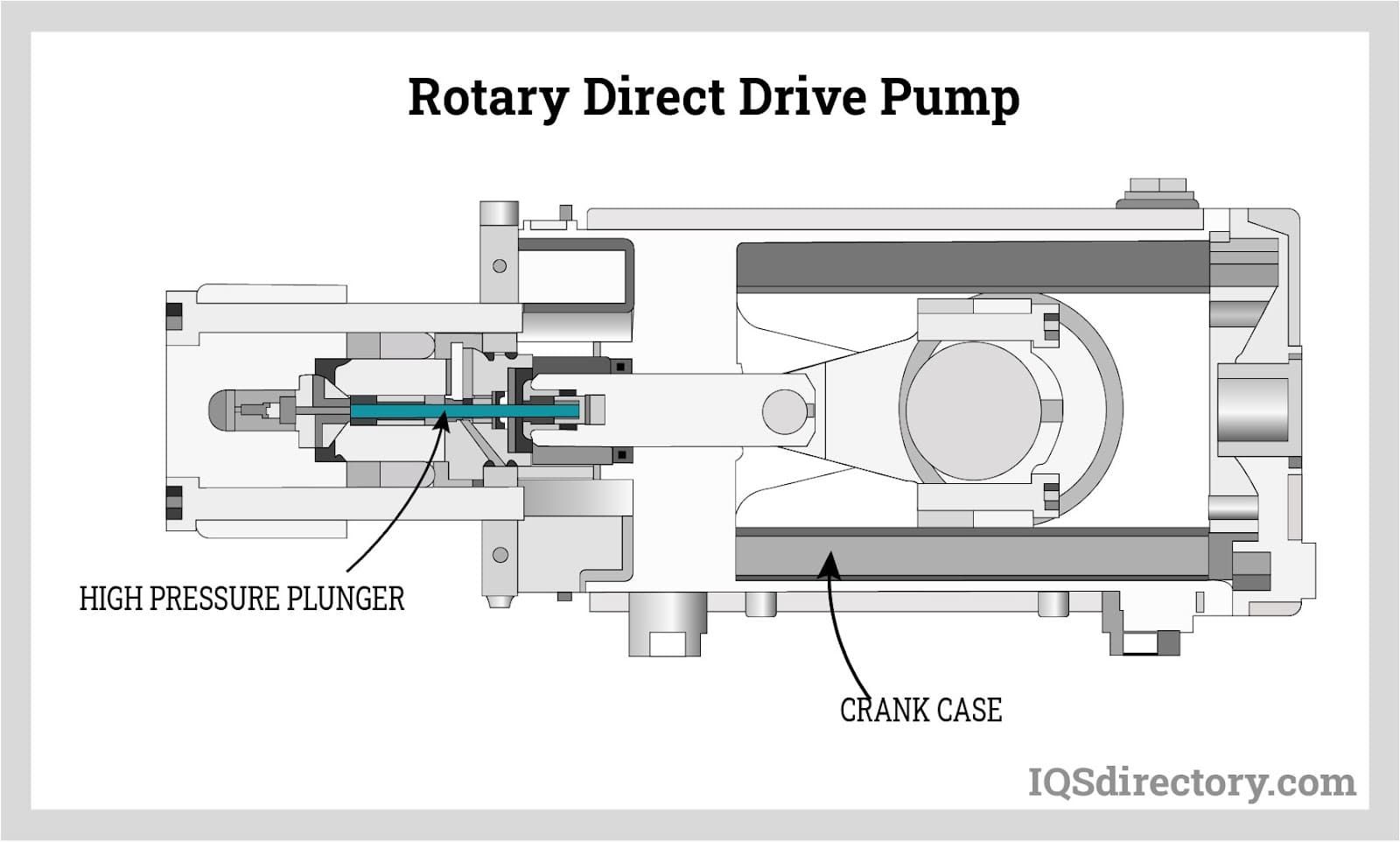
Several methods are used to pressurize the water, including linear intensifiers and rotary direct drive pumps. The two types of pumps have a motor, water filters, control systems, and sensors.
Linear intensifier pumps use pressurized hydraulic oil at a pressure of 3000 psi. Low pressure oil pushes against a piston that has a face area that is 20 times larger than that of the high pressure plunger that pushes against the water. Since the size of the low pressure pump is 20 times larger than that of the high pressure one, the pressure on the larger plunger is intensified 20 times, yielding a pressure of 60,000 psi.
A direct drive rotary pump does not include hydraulic oil. It has an electric motor that rotates a crank that drives pistons that generate the water pressure. Direct drive pumps have 30 hp motors with an inlet that supplies water to the pump.
High Pressure Tubing
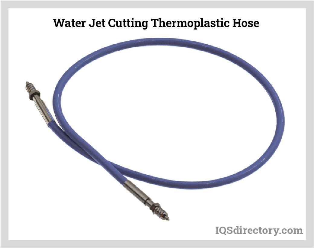
The pressurized water from the pump travels through high pressure tubing to the cutting head. High pressure tubing has excellent yield and tensile strength with an exceptionally smooth interior surface. It is produced from cold worked stainless steel or thermoplastic pressure hose in sizes from 0.25 inches up to 0.563 inches and comes in a wide variety of lengths to fit the design of the water jet cutter.
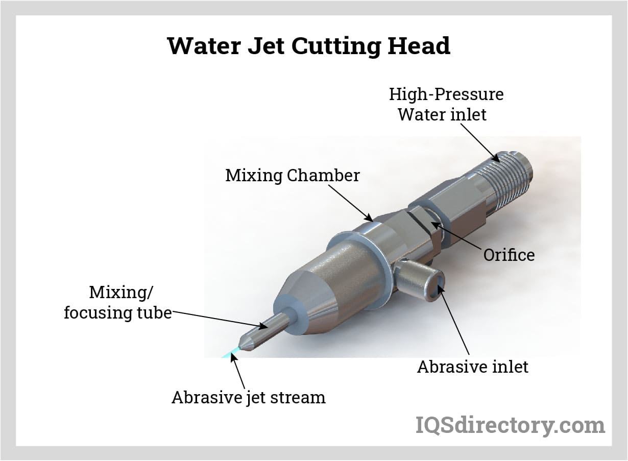
Water Jet Cutting Head
The pressurized water passes through the orifice of the cutting head, which is a diamond, ruby, or sapphire with a hole smaller than the point of a pin. As the water passes through, its velocity radically increases to over 90,000 psi or 2500 mph. The cutting process is directly affected by the power provided by the cutting head. A precision tooling cutting head, when used properly, can last from 500 to 1000 hours.
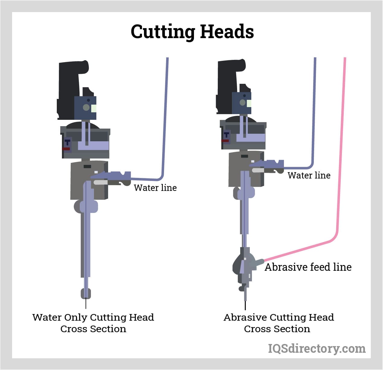
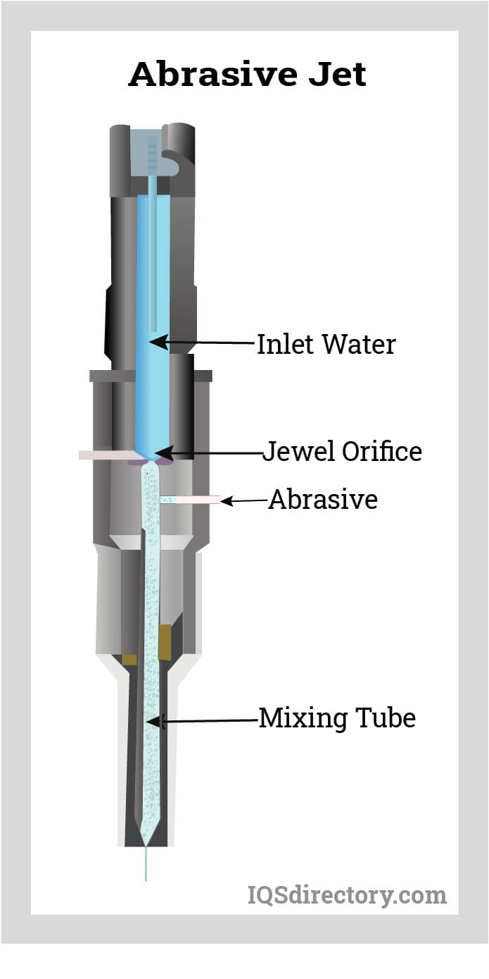
The image below has an example of two cutting heads, which are water only and water with abrasive. The difference between the two types can be seen in the red tube carrying the abrasive to the water stream.
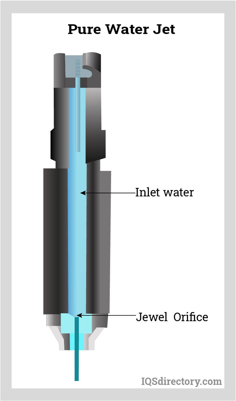
Pure Water Jet Cutters
Pure water jet cutters are the original form of water jet cutting tool. They are used due to the fact that they create less moisture on the surface of the workpiece than is created by touching it. They have a thin stream that cuts excellent detailed geometries with limited material loss. The construction of a pure water jet cutter has a jewel with rubies being excluded and unsuitable for work with pure water. The stream travels at Mach 2 for 40,000 psi and Mach 3 for 60,000 psi.
Abrasive Water Jet Cutting System
In the abrasive water jet cutting system, an abrasive material is fed into the cutting head, where it is mixed appropriately with the water stream. The introduction of an abrasive makes the stream sharper and creates more effective cutting. The addition of an abrasive makes a water jet cutter capable of cutting anything regardless of its hardness or thickness.
With an abrasive water jet cutter, the stream accelerates the abrasive material that erodes away the surface of the material being cut. An abrasive water jet cutter is 1000 times more powerful than a pure water jet cutter. The stream is larger in diameter and capable of cutting materials that are ten inches thick without creating heat or mechanical stress.
Laser Cutting Operation:
Laser cutting using a knife as a tool involves several steps:
- First, the design is prepared using software, specifying the desired dimensions and shapes.
- Then, the material to be cut is securely placed on the cutting bed of the laser cutter.
- The laser cutter emits a high-powered laser beam that is focused onto the material, causing it to heat up and melt or vaporize along the predetermined cutting path.
There are different types of laser cutting methods used in the process. One common method is vector cutting, where the laser follows a continuous path along the outline of the design to cut through the material. Another method is raster engraving, where the laser moves back and forth in a grid pattern to create detailed engravings or markings on the material's surface. Additionally, some laser cutters have the capability for 3D engraving, which allows for cutting or engraving on curved surfaces.
There are various machines used in the laser cutting process. One example is the CO2 laser cutter, which is commonly used for cutting and engraving materials such as wood, acrylic, and paper. Another example is the fiber laser cutter, which is highly efficient for cutting metals like steel and aluminum. Additionally, there are specialized laser cutters for specific applications, such as the UV laser cutter for cutting delicate materials or the galvo laser cutter for high-speed precision cutting.
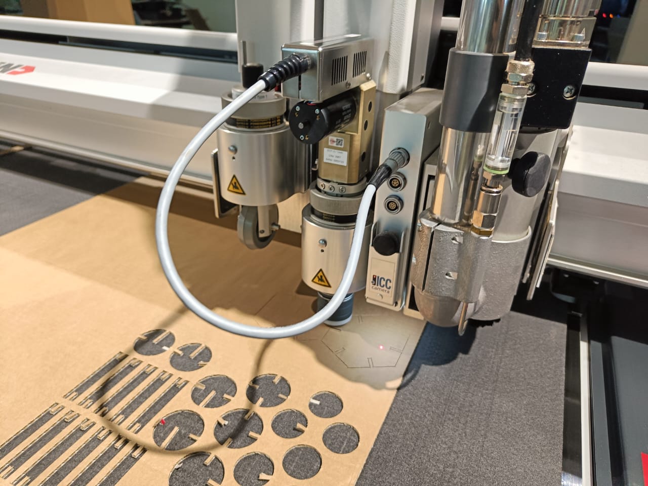
Active modes of cutting in knives: Oscillatory and ultrasonic modes of actuation
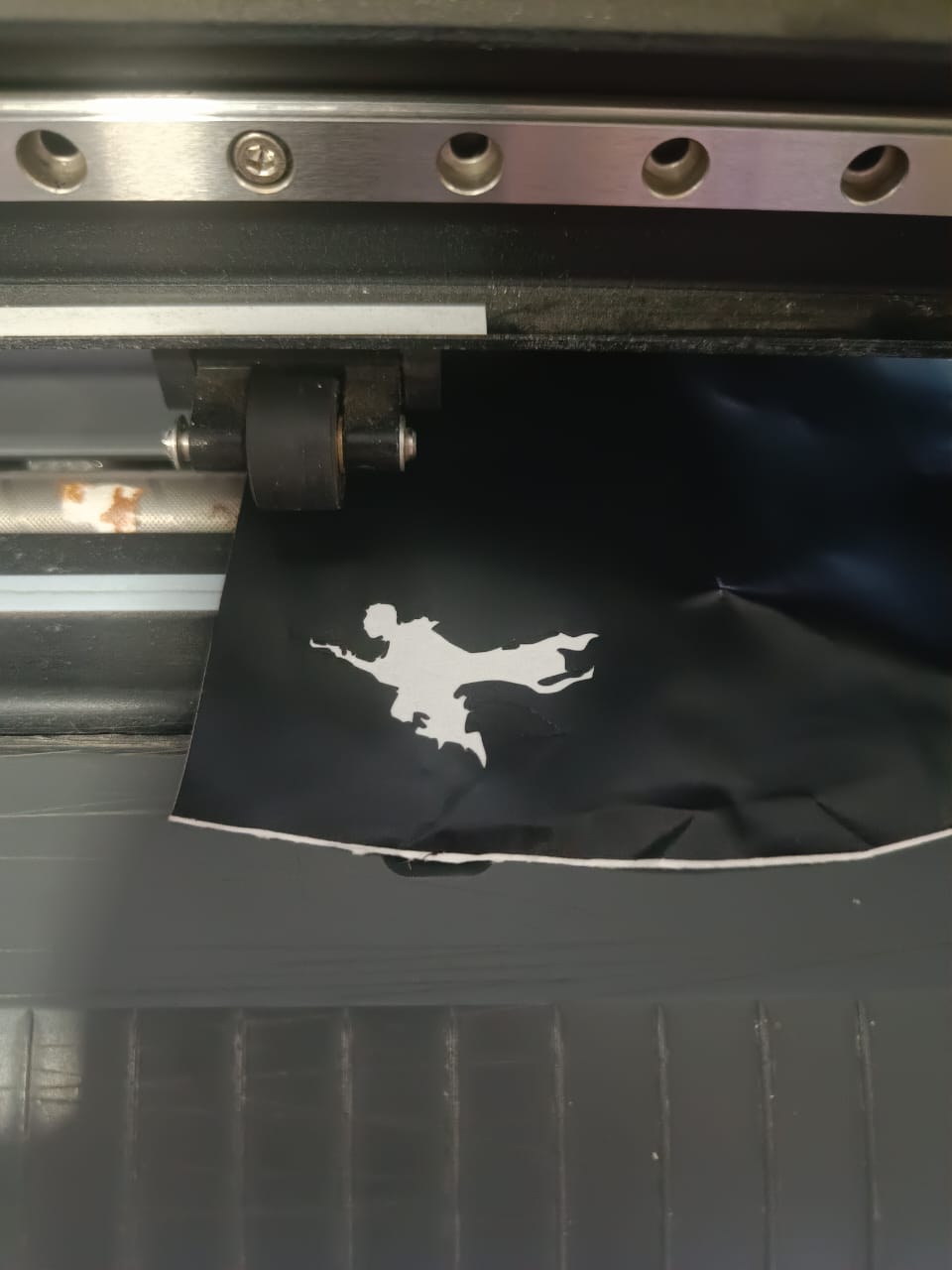
Printing and boundary cutting occurring in the same machine.
Cutting experience using the Vinyl Cutter
A vinyl cutter is a computer-controlled machine used to precisely cut designs, patterns, or lettering out of vinyl sheets or rolls. These machines are commonly used in the creation of signs, decals, stickers, and various other decorative or promotional materials.
Principles used in a vinyl cutter:
- Blade and Cutting Mechanism: Vinyl cutters typically employ a small, sharp blade that is controlled by a motor. The blade moves along the X and Y axes to cut the vinyl material according to the design programmed into the machine's software.
- Material Feed System: Vinyl sheets or rolls are fed into the cutter using rollers or other mechanisms. The material is held securely in place during cutting to ensure accurate results.
- Control Software: Vinyl cutters are controlled by dedicated software, which allows users to create or import designs, specify cutting parameters such as speed and pressure, and send instructions to the cutter.
- Vector Graphics: Designs for cutting are typically created as vector graphics, which define shapes using mathematical equations rather than pixels. Vector graphics are scalable and allow for precise cutting at any size.
Steps for preparing files using Inkscape for cutting in a vinyl cutter:
- Create or Import Design: Start by creating your design or importing an existing design into Inkscape. Inkscape is a free and open-source vector graphics editor that is commonly used for designing artwork for vinyl cutting.
- Convert Text to Paths: If your design includes text, convert it to paths to ensure that the vinyl cutter will cut the text as shapes rather than attempting to interpret fonts.
- Set Cutting Parameters: Determine the cutting parameters for your design, such as the cutting speed, blade pressure, and whether to perform a kiss cut (cutting through the vinyl but not the backing material) or a complete cut (cutting through both the vinyl and backing material).
- Arrange Design Elements: Arrange your design elements within the workspace to optimize material usage and minimize waste.
- Mirror Image (if necessary): If you're cutting adhesive vinyl for application to a surface (e.g., for decals or stickers), you may need to mirror your design horizontally before cutting to ensure that it appears correctly when applied.
- Export as SVG: Once your design is ready, export it as an SVG (Scalable Vector Graphics) file, which is a common file format used for vector graphics that can be imported into vinyl cutter software.
- Import into Vinyl Cutter Software: Open your SVG file in the software provided with your vinyl cutter. This software will allow you to adjust cutting parameters, set the origin point for cutting, and send the design to the vinyl cutter for cutting.
- Load Material and Initiate Cutting: Load your vinyl material into the cutter, ensuring it is properly aligned and secured. Then, initiate the cutting process through the software, and the vinyl cutter will begin cutting your design according to the parameters you've specified.
Some glimpses from my cutting activities from the Vinyl Cutter
I edited the files I wanted to cut using Inkscape.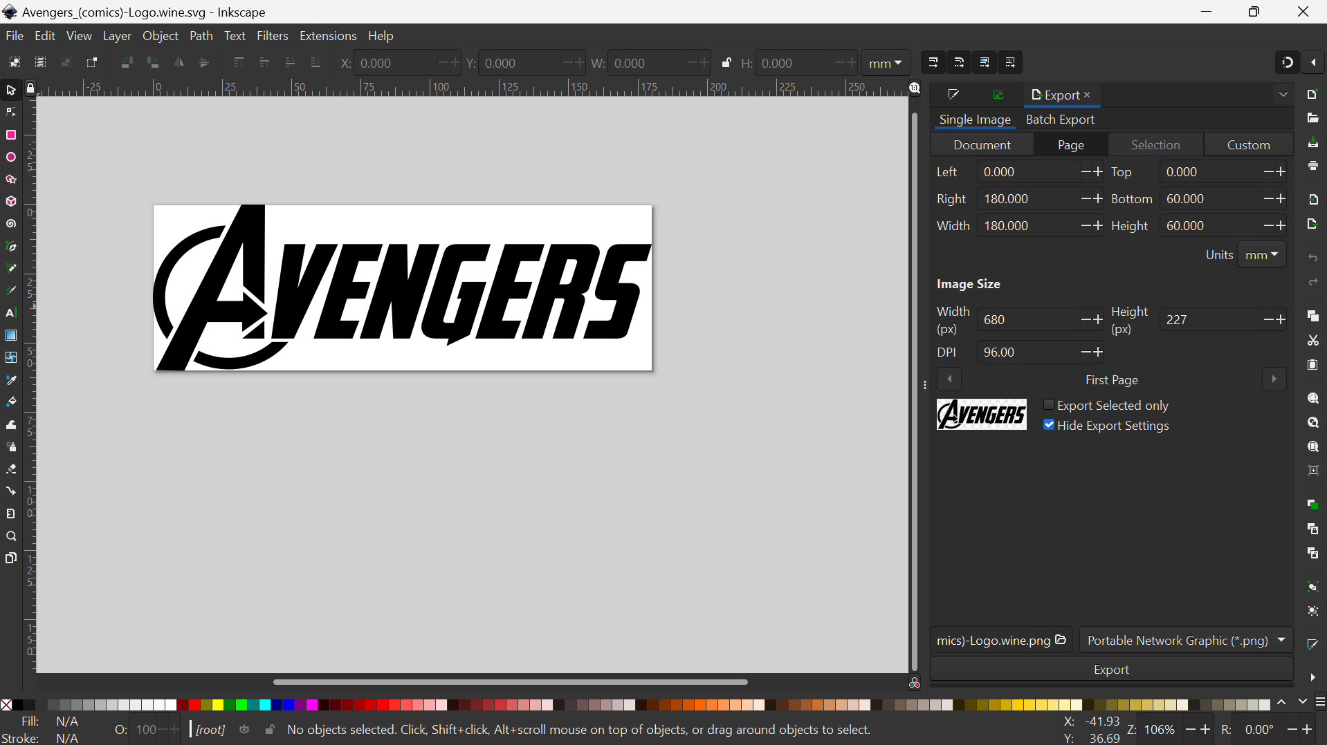
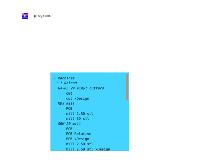
Accessing mods interface
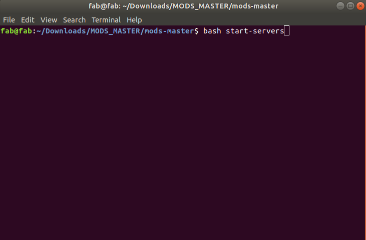
Once opened, right click to select programs>open programs>(the machine and the process).
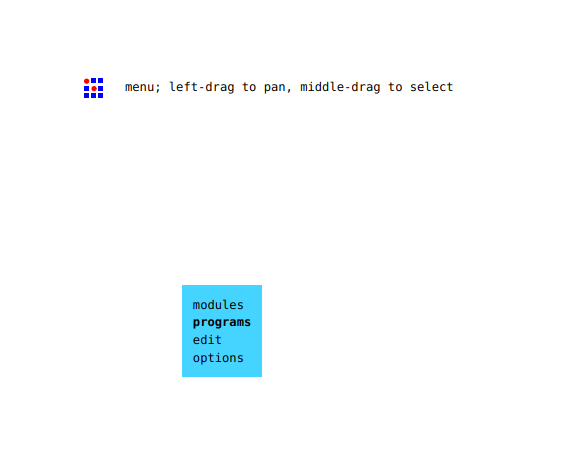

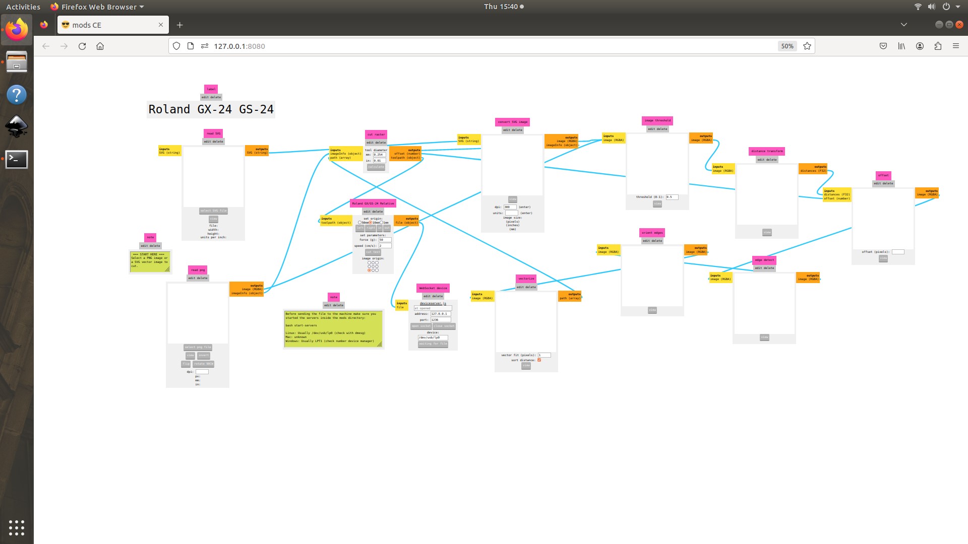
In the interface, please select the file, set the origin and values. There is a view option to see the path the vinyl cutter will follow to cut the image.
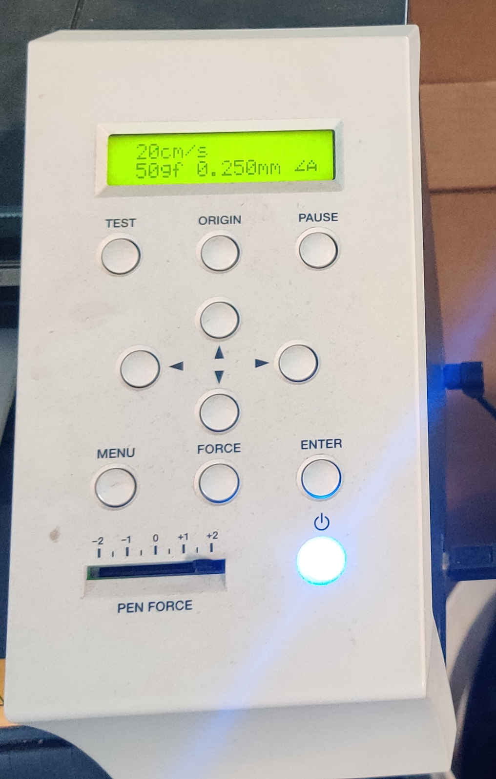
Interface of the Vinyl Cutter for setting origin and speed
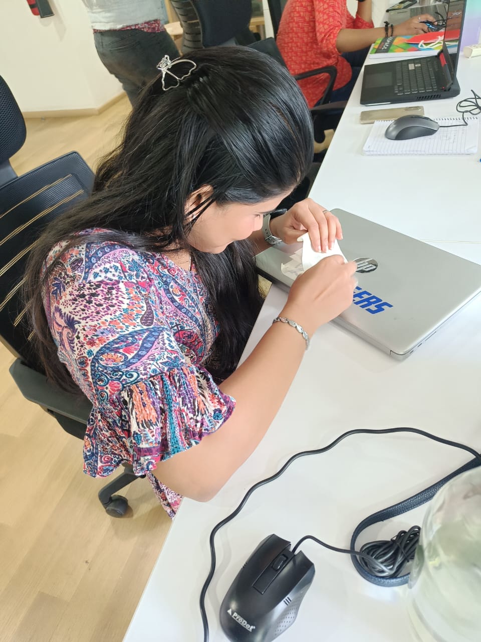
A glimpse of me transferring the sticker to my laptop using a masking tape
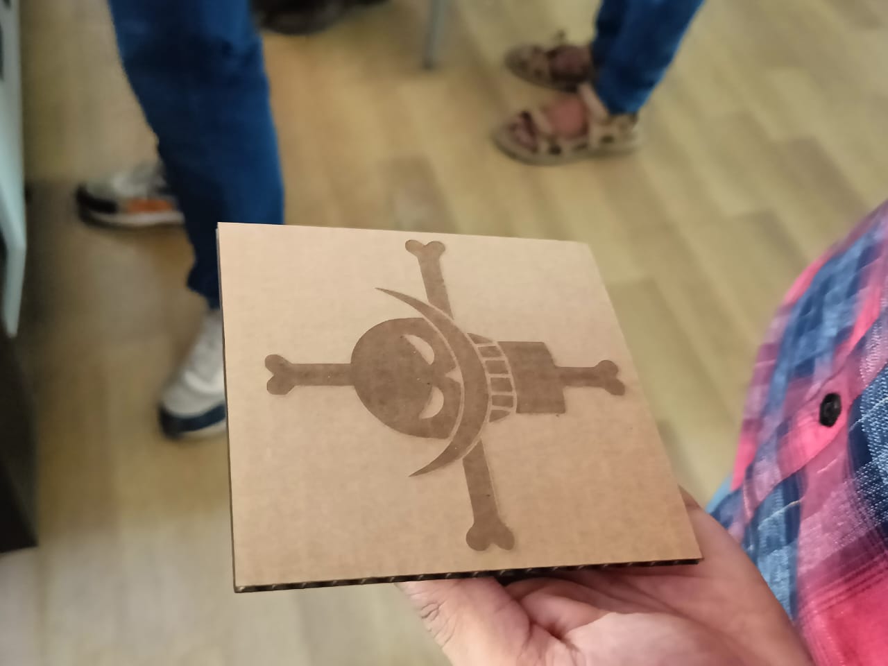
Left over piece after removing the Harry Potter Sticker that I had created
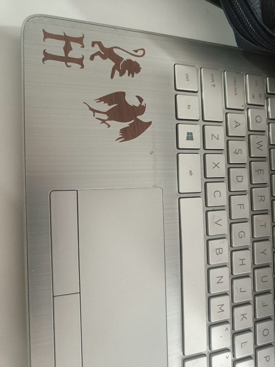
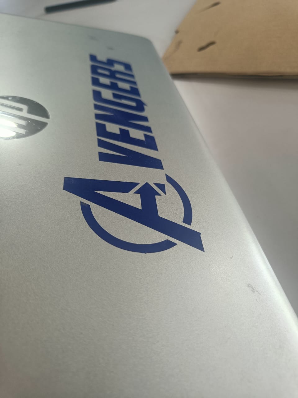
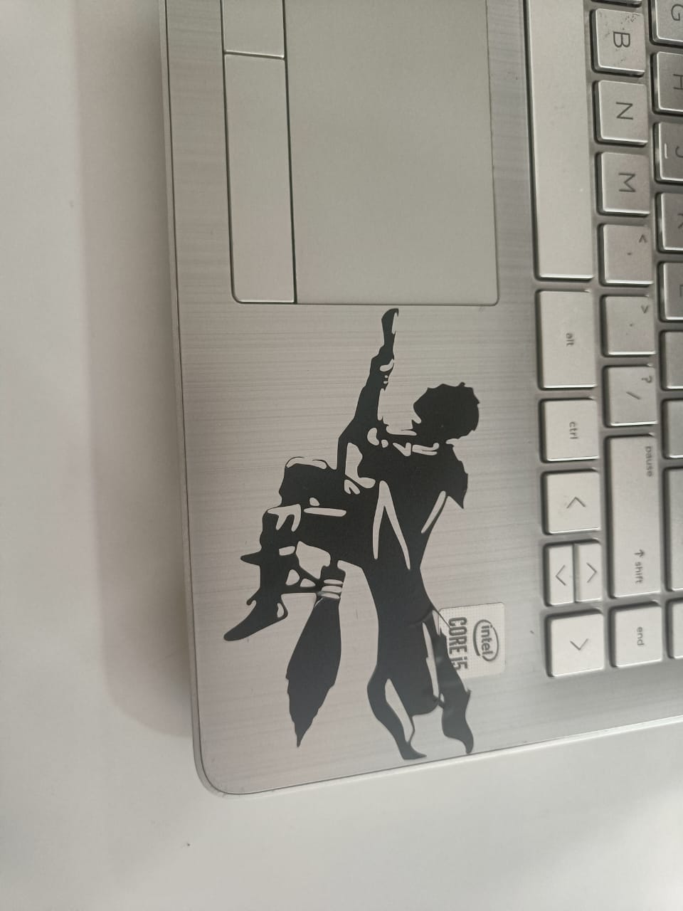
Stickers transferred to my laptop
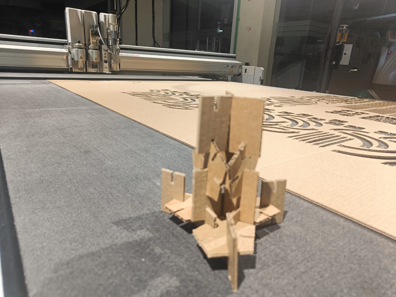
Results from a Large Format Laser Cutter:
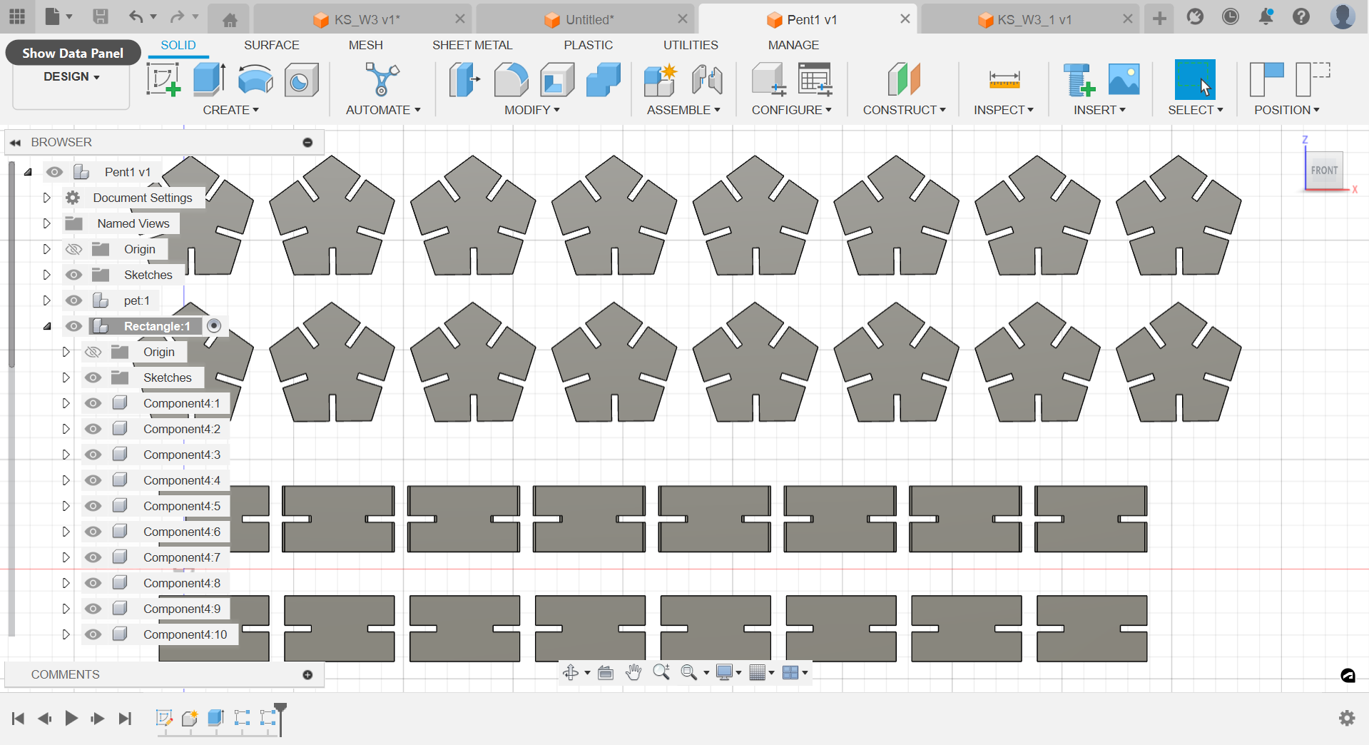
Designing Parametric designs using Fusion 360
Parametric design is a design approach that uses parameters or variables to define the characteristics and relationships of a model. These parameters can include dimensions, constraints, relationships, and other design elements. With parametric design, changes to one aspect of the model automatically propagate through the entire design, ensuring consistency and facilitating rapid iteration.
Autodesk Fusion 360 is a powerful computer-aided design (CAD), computer-aided engineering (CAE), and computer-aided manufacturing (CAM) software suite that supports parametric design principles. Here's an overview of the process of making a parametric design using Autodesk Fusion 360:
- Sketching: Begin by creating 2D sketches of the basic shapes and features that will form the foundation of your design. Fusion 360 offers various sketching tools, such as lines, circles, rectangles, and arcs, to create precise geometry.
- Defining Parameters: Once you have created your sketches, use Fusion 360's parameter management tools to define dimensions and constraints. Parameters allow you to specify numerical values for dimensions, angles, and other design properties, making your design flexible and easily modifiable.
- Adding Constraints: Apply geometric constraints to your sketches to define relationships between different elements. Constraints ensure that specific geometric conditions are maintained, such as parallelism, perpendicularity, tangency, and symmetry.
- Creating Features: Use Fusion 360's feature-based modeling tools to extrude, revolve, sweep, loft, or fillet your sketches to create 3D solid geometry. Features are building blocks that add depth and complexity to your design.
- Modifying Geometry: With parametric design, you can easily modify the dimensions, shapes, or positions of your geometry by adjusting the parameters you defined earlier. Fusion 360's timeline-based design history allows you to revisit and edit any step of the design process without losing the associativity between features.
- Assembling Components (if applicable): If your design consists of multiple parts or components, use Fusion 360's assembly environment to assemble and position them relative to each other. Parametric relationships can be established between components to maintain their relative positions and alignments.
- Testing and Simulation (if applicable): Fusion 360 offers simulation and analysis tools that allow you to evaluate the performance and behavior of your design under various conditions. Conducting simulations early in the design process helps identify potential issues and optimize your design for performance and manufacturability.
- Documenting and Sharing: Generate drawings, renderings, or animations of your parametric design to communicate your ideas effectively with stakeholders, clients, or manufacturing partners. Fusion 360 provides tools for creating detailed technical drawings and high-quality visualizations.
To cut parametric designs in DXF format using a Zund Machine's laser cutting tool, you'll need to follow a series of steps that involve preparing your design, exporting it to the DXF format, and then setting up the cutting parameters on the Zund Machine's control software. Here's a general process to achieve this:
- Design Preparation:
- Create or import your parametric design into a CAD (Computer-Aided Design) software such as Autodesk Fusion 360, SolidWorks, or AutoCAD.
- Ensure that your design is fully defined and parametrically driven, meaning that it is based on mathematical relationships and parameters that can be adjusted later if needed.
- Check the dimensions and scale of your design to ensure it matches the intended size for cutting.
- Export to DXF:
- Once your design is ready, export it to the DXF (Drawing Exchange Format) file format. This format is commonly used for exchanging CAD drawings between different software applications and is compatible with most laser cutting machines, including Zund Machines.
- Make sure to specify the appropriate units (such as millimeters or inches) and other settings when exporting to DXF to ensure compatibility with the Zund Machine's control software.
- Setting up Zund Machine:
- Prepare the Zund Machine for laser cutting by ensuring that it is properly calibrated and configured for the material you will be cutting.
- Load the appropriate laser cutting tool into the machine, ensuring that it is suitable for the material and thickness you'll be working with.
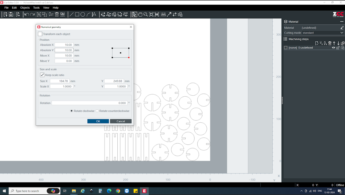
- Importing DXF File:
- Launch the control software for the Zund Machine.
- Import the DXF file containing your parametric design into the Zund control software. This can typically be done through a file import or open command within the software interface.
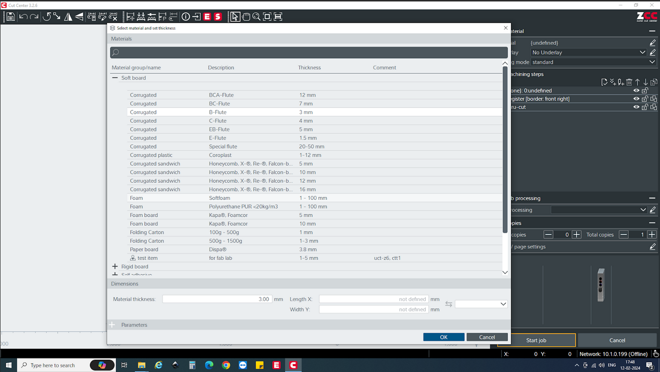
- Setting Cutting Parameters:
- Configure the cutting parameters in the Zund control software based on the material type, thickness, and desired cutting quality.
- Specify the cutting path and any additional parameters such as cutting speed, laser power, and focus depth. These parameters may vary depending on the specific requirements of your design and material.
- Preview and Simulation:
- Use the Zund control software to preview the cutting path and simulate the cutting process. This allows you to verify that the design will be cut accurately and efficiently before actually starting the cutting operation.
- Running the Cutting Job:
- Once you're satisfied with the cutting parameters and preview, initiate the cutting job on the Zund Machine.
- Monitor the cutting process to ensure that it proceeds smoothly and that there are no issues with the material or cutting tool.
- After the cutting operation is complete, remove the cut parts from the machine and perform any necessary finishing or post-processing steps.


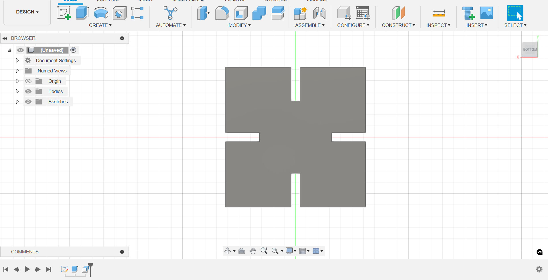
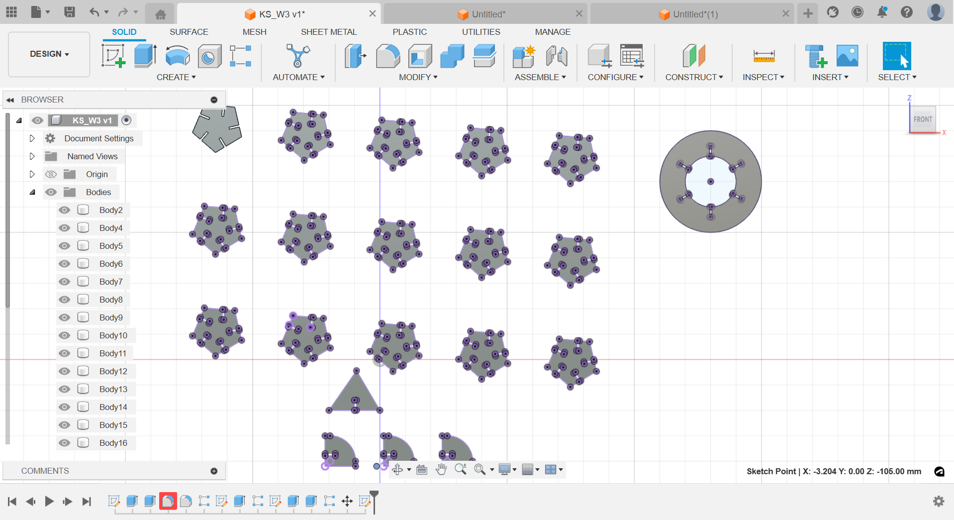
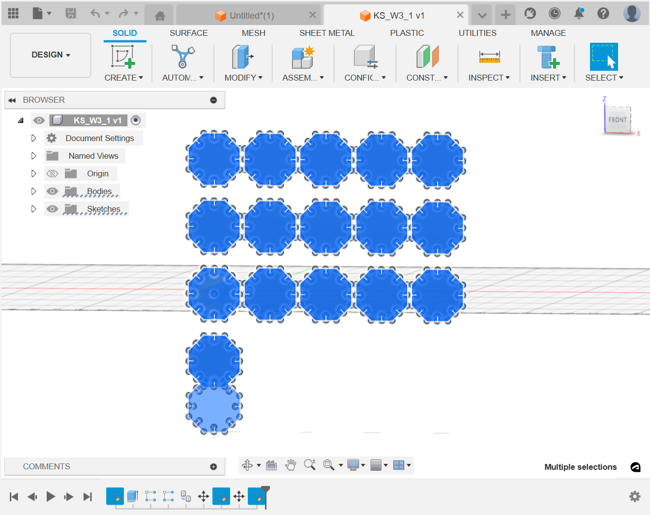
Some screenshots from the Fusion interface: